The TTP-Amp: Rediscovering the Warm Sound of Vintage Hi-Fi
A personal journey through thirty preamplifiers, forgotten tube circuits, an unusual homemade tube-rectified power supply, vintage European loudness compensation, recycled NAD electronics and some rather surprising listening experiments. With a little help — and occasional confusion — from AI.
Back to an old hobby
It all started rather unexpectedly. The purchase of a second-hand Creek headphone amplifier and some vintage Audio Alchemy equipment brought me back into a hobby I had largely abandoned around 2018. For decades I had spent countless hours experimenting with audio electronics: building, modifying and comparing equipment, particularly preamplifiers. I estimate that at least thirty different preamps have passed through my hands: tubes, transistors, hybrids, triodes, pentodes, Class A designs and op-amps. Some were expensive, others homemade. None really convinced me for very long.
Eventually I lost much of my enthusiasm for serious audio listening. I returned to a simple streaming setup and treated music increasingly as pleasant background sound. Then, while experimenting with my recently acquired vintage equipment, I decided to retrieve one of my last DIY creations from storage: a tube preamplifier I had built around 2018. I connected it, started listening, and was genuinely surprised. This little homemade device still sounded wonderfully warm, relaxed and enjoyable. Perhaps it was the most successful preamplifier I had ever built. Why had I almost forgotten about it?
Does a preamplifier really need to amplify?
One of my longstanding frustrations with commercial preamplifiers is their excessive gain. Modern digital sources commonly deliver approximately 2 V RMS, whereas older tuners and other line-level sources often operated at considerably lower levels. Yet many preamps still provide tenfold voltage amplification or more. Why? In a normal domestic setup, the result is that the volume knob rarely moves beyond the nine or ten o’clock position. Fine adjustment becomes difficult and channel imbalance may become noticeable at the lowest settings.
In many situations, a modern preamplifier is better described as an active attenuator. It selects an input, reduces the signal to a comfortable listening level, provides suitable impedances and possibly performs some useful tonal correction. Substantial amplification is often unnecessary. I wanted a simple design with modest gain, perhaps two to four times, ideally using a single triode per channel.
Why not use an entirely passive preamplifier, simply a potentiometer between source and power amplifier? I have tried that too. Many times, in fact. The concept is wonderfully simple, but my listening experiences were rarely satisfying. I often found passive arrangements rather empty or lacking in vitality. This is a subjective observation, not a universal law. Source impedance, cable capacitance, amplifier loading and volume-control characteristics can all influence the result. But it remained an observation that shaped my experiments.
Whatever happened to the warm European sound?
Gradually I rediscovered the character of European amplifiers from the 1960s and early 1970s: Philips, Grundig, Telefunken, Dual, Saba, Nordmende and Transmare. Models such as the Philips 590, Dual CV12 and Transmare A500 are interesting reminders of a different design philosophy. These amplifiers were not always perfectly neutral, nor were they intended to be. Many offered a warm, full-bodied presentation, often supported by carefully designed contour or physiological volume controls.
The idea was based on the equal-loudness characteristics of human hearing, commonly associated with Fletcher and Munson. At low sound-pressure levels, our sensitivity to bass decreases considerably, and our perception of treble also changes. An electrically flat response does not necessarily produce a subjectively balanced sound when listening quietly. By adding some bass and perhaps a little treble, a preamplifier can compensate for this effect.
Traditional loudness circuits often used special volume potentiometers with an additional tap. As the volume was reduced, bass and treble compensation increased. At higher settings, the response approached flat. Clever, but not automatically successful. Different sources, loudspeakers, rooms and listening habits make a universally correct compensation curve difficult to achieve. I spent considerable time experimenting with tapped potentiometers and old service-manual circuits, without ever finding a completely satisfactory solution.
There was another difference I noticed. Many classic European contour circuits produced a relatively gentle U-shaped frequency response, whereas some later loudness implementations seemed to produce a more dramatic V-shaped boost, with booming bass and exaggerated treble. I never liked that approach. My objective was more subtle: a little warmth and body, without turning every recording into a spectacular hi-fi demonstration.
At my usual listening level of approximately 65–70 dB, such compensation can make a real difference. I rarely want to reproduce concert sound-pressure levels in my living room anymore. And with age, aggressive treble has become less attractive. Does that mean my preamplifier should deliberately colour the sound? Yes. Why not? If the objective is musical enjoyment, I see no reason to treat perfect electrical neutrality as a sacred obligation.
2018: starting with the Audio Innovations L2
One circuit that attracted my attention was the Audio Innovations L2, a relatively simple tube preamplifier using half an ECC82 per channel. Its modest amplification, achieved partly through feedback from output to input, seemed a promising starting point. I liked the basic principle but wanted more control over its tonal character. The ECC82, also known as the 12AU7, and its octal relative, the 6SN7, were obvious candidates: widely available, familiar, affordable and suitable for modest-gain circuits.
What followed was a prolonged period of trial and error. I studied old European service manuals, simulated circuits in LTspice, changed resistor and capacitor values, and listened repeatedly. I experimented with correction through the negative-feedback path as well as frequency-dependent cathode networks. Sometimes the bass became too heavy, sometimes the sound lost its warmth, and sometimes a seemingly insignificant component change made the result more enjoyable.
I eventually arrived at a rather unconventional hybrid correction system. Several RC networks worked together to create a mild U-shaped response. In contrast with traditional loudness compensation, the correction was fixed rather than volume-dependent. Since I normally listened at a fairly consistent level, that was an acceptable compromise. A switch or adjustable component could still provide different degrees of bass correction.
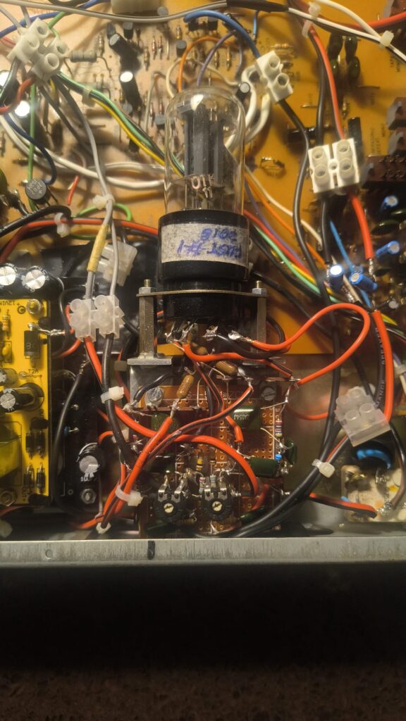
Today I find it amusing how little I documented the final result. I recently discovered an almost illegible handwritten sketch and some old LTspice files, but the exact development history had largely vanished from my memory. Opening the old preamp was another surprise: there were considerably more components involved in shaping that gentle contour than I remembered. Apparently I had spent much more time optimizing the circuit than I had given myself credit for.
An AliExpress circuit board and a rather clever 12 V solution
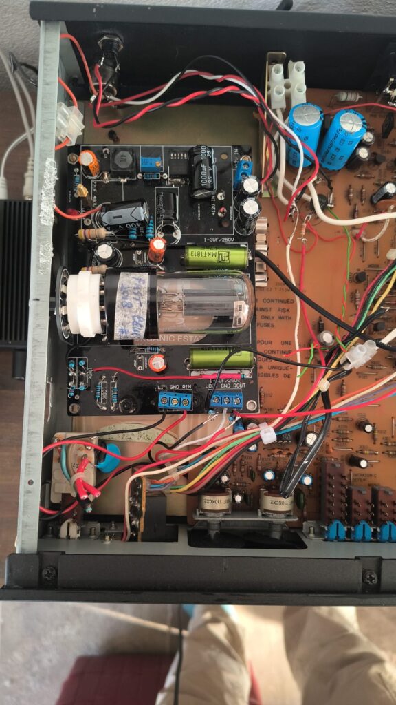
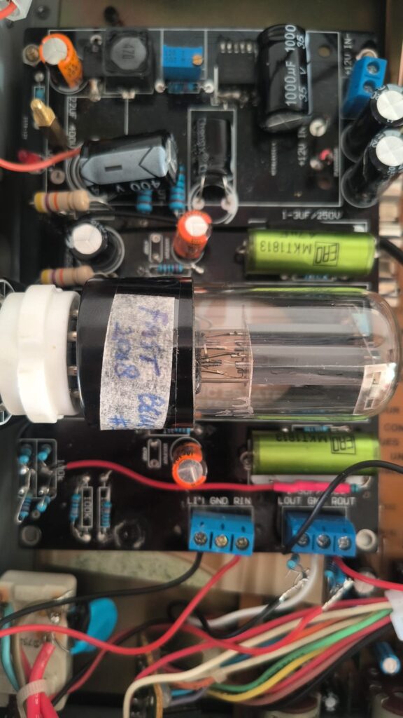
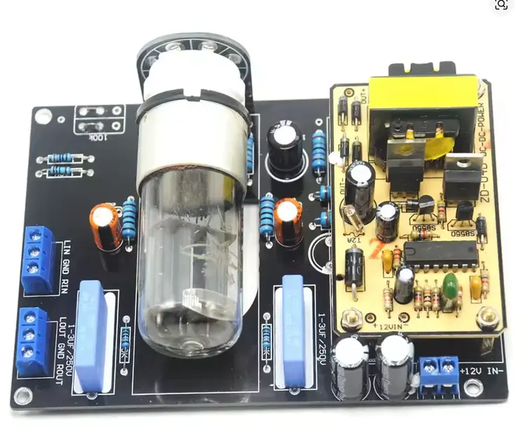
During those experiments I discovered an inexpensive Chinese 6SN7 stereo preamplifier board. It was attractive for several reasons. A single 6SN7 contains two triodes, enough for both stereo channels, and the tube was mounted horizontally, making installation inside an existing enclosure relatively easy. But the remarkable feature was the power supply: the entire board operated from an external 12 V supply.
On the board, a switching converter raised the 12 V to approximately 250 V for the anodes, while another converter provided the necessary heater voltage. I could therefore use a cheap recycled 12 V adapter from an old electronic device. Ingenious, although hardly the simplest imaginable tube amplifier! I had no complete schematic of the converter electronics, and that also made me slightly uncomfortable.
I stripped and modified much of the audio circuitry, experimenting with my own component values. The arrangement worked quite well, but I continued wondering whether a simpler and perhaps more traditional power supply might sound different. This became a separate adventure.
The unusual power supply: using an ECC82 or 6SN7 as a double diode
My first idea was to build a tube-rectified power supply. Conventional rectifiers such as the EZ80 or EZ81 would have been obvious choices, but they were not particularly attractive for this project. They required a suitable transformer, were relatively expensive compared with the ordinary small-signal tubes I already possessed, and did not naturally fit my low-voltage transformer concept.
Then I came across an interesting project by a Dutch hobbyist known as Tubejack. He had modified an old Akai tuner and generated a suitable tube supply voltage from a low-voltage transformer using a voltage-doubler circuit. His design used ordinary semiconductor diodes. It gave me an idea: why not replace those diodes with the two triode sections of an ECC82, each connected as a diode?
A triode can be used as a rectifier by connecting its grid to its anode, turning it into a two-electrode device. An ECC82 contains two independent triodes, so one tube can provide two rectifying elements. The same principle works with a 6SN7 or 12SN7, provided that the heater supply, pin connections, voltage ratings and current limits are respected. This was not a new invention in an absolute sense, although I arrived at it independently. Even today, examples of ordinary dual triodes being used in this particular way are relatively uncommon.
I obtained a small 30-0-30 V PCB transformer, providing approximately 60 V AC across its complete secondary winding. Combined with the tube-based voltage-doubler arrangement, it produced approximately 115–125 V DC under load — a useful supply for my modest single-triode preamplifier. The heater supply came from a recycled 12 V adapter, with a buck converter providing approximately 6.3 V where needed. It was an economical and wonderfully unconventional solution.
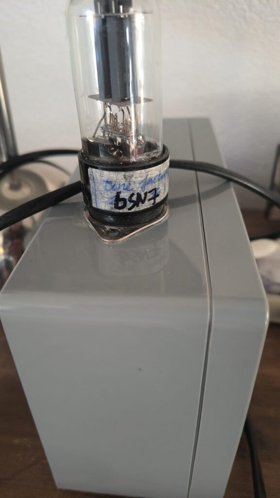
The earliest version used a 12SN7 as the double-diode rectifier. Later I built a neater external enclosure in which I could use an ECC82 or 6SN7 instead. The power-supply box also contains the symmetrical approximately ±24 V supply for the NAD electronics and the low-voltage supplies for the tube heaters. Keeping this assembly outside the preamplifier enclosure has another advantage: transformers and switching converters remain physically separated from the sensitive audio circuitry, reducing opportunities for hum and interference.
There are disadvantages to using a small-signal dual triode as a rectifier. Its voltage drop and permissible current are less favourable than those of a purpose-designed rectifier, and the operating conditions must remain within the tube’s ratings. Nevertheless, for this low-current application, the concept has proved useful. And, I must admit, there is something rather appealing about using an ordinary ECC82 or 6SN7 as a homemade rectifier. An unconventional solution to an unconventional problem.
But does the tube power supply actually sound better?
Here the story becomes more interesting. I arranged the circuit so that I could compare the original 250 V switching supply with my approximately 125 V tube-rectified supply. To my ears, the lower-voltage arrangement sounded clearly better: warmer, sweeter and more relaxed. Eventually I stopped using the 250 V supply almost entirely.
But what exactly was I hearing? Was the improvement caused by tube rectification, the absence of a high-voltage switching converter, the lower anode voltage or the changed operating point of the 6SN7? It would be much too easy to attribute everything to the romantic appeal of a glowing rectifier tube.
Consider three operating arrangements: 250 V with a 47 kΩ anode resistor, 125 V with approximately 22 kΩ, and 125 V with 47 kΩ. The second arrangement partly compensates for the lower supply voltage and can maintain a more comparable operating region. The third deliberately changes the tube’s load line and operating point, potentially increasing certain forms of harmonic distortion. In my listening experiments, the progression seemed to move from a somewhat cooler, more conventional sound toward the sweet, warm presentation I preferred.
This suggests an intriguing possibility: the desirable character may not be due primarily to the power supply itself, but to how the tube behaves under these different operating conditions. A modest amount of low-order harmonic distortion, particularly second harmonic, might contribute to the perceived warmth. However, the distortion spectrum and the precise relationship with listening impressions have not been conclusively measured.
My objective was never to maximize distortion. I wanted a gentle tonal balance and controlled behaviour. Preliminary calculations and simulations suggest that distortion could remain below approximately 1% at normal listening levels, depending on the operating point. That is hardly alarming when viewed against the standards of historical hi-fi equipment. But it is worth remembering that calculations are not measurements, and that the tube’s actual operating point matters.
So here is my first question for technically minded readers: if a lower-voltage tube circuit sounds more pleasant, are we hearing the rectifier, the changed tube operating point, a different distortion spectrum, or some combination of these? The obvious next step would be a controlled comparison at matched operating points and output levels, preferably including an equivalent semiconductor-rectified supply.
A detour through the Dual CR-220
Another experiment from this period still puzzles me. I obtained the preamplifier and tone-control board from a Dual CR-220 receiver. The original equipment had the kind of contour characteristic I admired, so I fitted new potentiometers and adapted the relevant components for separate use. I could even vary the correction using an additional attenuator.
To my disappointment, the result sounded rather heavy and cumbersome, regardless of which power amplifier I used. Yet I remembered the original Dual receiver as having a much more enjoyable, lively sound. How could essentially the same circuit behave so differently?
Of course, the surrounding impedances, potentiometer characteristics, gain structure, component values, power supply and interaction with the rest of the original receiver could all be important. In retrospect, I also suspect that my replacement potentiometers may not have reproduced the intended contour. AI can now help me calculate suitable values for the actual controls I used, so I intend to revisit this board. Nevertheless, the experiment remains an early warning: a familiar schematic does not necessarily reproduce a familiar sound when removed from its original environment.
2026: giving the NAD 1240 a second life
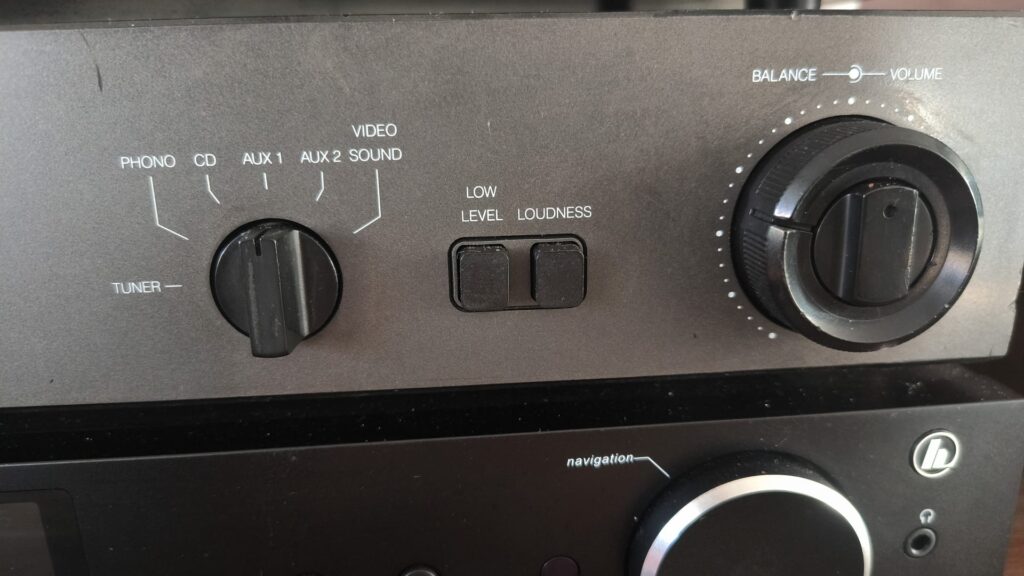
My 2018 TTP-Amp was installed inside an old NAD preamplifier enclosure, using its input selector, volume and balance controls while routing the signal through my own 6SN7 circuit to a separate output. I have always liked the inexpensive NAD 1240. I owned several more prestigious NAD preamps over the years, but this modest model was one of my favourites. Its original op-amp circuitry sounds surprisingly good to me, despite costing very little in component terms.
By late 2026, I had another NAD 1240 available, as well as boxes full of tubes, old circuit boards, switches, resistors, capacitors and other leftovers. Reusing this material is part of the pleasure of DIY. Why buy an expensive new chassis when a perfectly serviceable old preamplifier already offers a decent enclosure, excellent controls and convenient connections?
I decided to build a second TTP-Amp using the NAD as a working experimental platform. The Chinese 6SN7 board was stripped and modified again, and the original 250 V switching converter was removed. My separate tube power supply would provide the anode voltage instead. Crucially, I wanted to retain the original NAD circuitry rather than sacrifice it to the conversion.
The NAD has two preamplifier outputs. One remains available for the original solid-state circuit, while the other serves the new tube stage. I also reduced the substantial gain of the NAD op-amp circuitry to approximately unity. This was not entirely trivial, because the NAD’s tone-control network forms part of its feedback arrangement. Changing the feedback to reduce gain also risks changing the operation of the bass and treble controls.
After several attempts, I obtained a useful arrangement that retains volume, balance, input selection, bass and treble controls, mono switching and bass EQ. I reused the original INFRA OFF switch for tone-control routing and bypass functions. The LOW LEVEL function also proved useful for adjusting the available volume-control range. With the additional switching possibilities, I can now listen through the NAD alone, through the tube stage, or through a combination of the NAD op-amp and the tube stage, with the desired tonal compensation enabled or disabled.
The result is not a minimalist purist’s dream. But it is a remarkably flexible laboratory for listening experiments, using equipment that might otherwise have remained on a shelf.
Another small adventure: interchangeable tubes
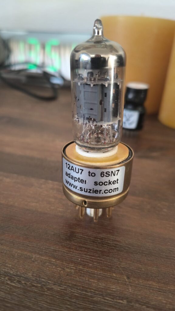
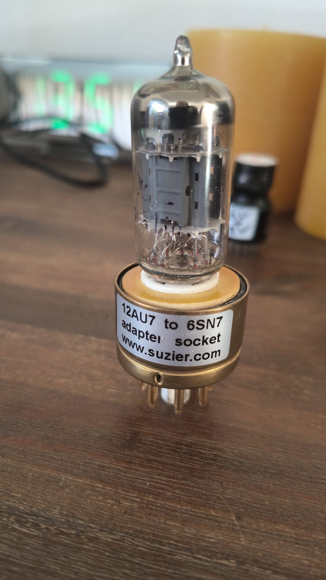
Over the years I have collected and made several adapters that allow different tubes to be used in the same equipment. The ECC82 is a nine-pin noval tube; the 6SN7 and 12SN7 use octal bases. Their heater requirements also differ, and the ECC82 itself offers alternative heater connections for 6.3 V or 12.6 V operation.
With suitable adapters and switchable heater arrangements, I can experiment with ECC82, 6SN7 and 12SN7 types in both the audio circuitry and the rectifier supply. This is convenient, but potentially dangerous. Incorrect pin assignments or heater configurations can damage tubes or equipment. When I recently rediscovered some of my old homemade adapters, I had to spend hours reconstructing what they actually did. Apparently documenting experiments has never been my strongest quality.
The whole arrangement is rather typical of my DIY approach: maximum reuse, modest expense, some unorthodox ideas and an occasional reminder that electricity is less forgiving than imagination.
Can AI reconstruct the sound of 2018?
At this point I introduced a new participant into the process: artificial intelligence. In 2018, all my calculations had been performed with LTspice, service manuals and plenty of trial and error. In 2026, I could ask ChatGPT, Gemini and Claude to examine old sketches, explore component values and calculate alternative circuits. I also wanted to discover just how useful these systems had become for an electronics hobbyist.
The results were fascinating and sometimes exasperating. AI could help calculate individual RC networks and explore frequency-response curves, particularly for a relatively simple single-triode circuit. Gemini was especially useful in several of these tasks. But drawing correct electronic schematics proved remarkably difficult. Components were misplaced, wires disappeared and errors that had supposedly been corrected repeatedly returned. Analysing the complete NAD 1240 feedback and tone-control circuit also produced inconsistent results from multiple AI systems.
One lesson quickly became clear: an AI-generated circuit diagram should not be treated as a verified construction drawing. My original Dutch-language articles deliberately show some of this imperfect development process, including incorrect intermediate schematics. They document how difficult it can be to work with AI on analogue electronics, rather than presenting an artificially polished and faultless design history.
Still, AI offered an opportunity I had not previously possessed. Could we calculate new arrangements producing roughly the same desired frequency response as TTP-2018, while allowing more flexibility and fewer interacting components?
Three different ways of producing the same contour
Method 1: the original hybrid active correction. TTP-2018 uses a combination of frequency-dependent negative feedback and cathode-network correction. The result emerged from years of experimentation rather than a single clean theoretical calculation. It contains more components than I would ideally like, and the correction is not easily bypassed. Nevertheless, this is the arrangement that still sounds best to me.
Method 2: passive loudness before a relatively linear tube stage. The idea behind TTP-2026 was to separate two functions. The tube would provide modest amplification with an approximately flat response, while a passive network around the existing NAD volume control would generate the desired European-style contour. AI helped me adapt the network to the actual 20 kΩ B-taper volume potentiometer and the surrounding circuit. This solution offered much greater switching flexibility, including the possibility of listening without any correction.
Method 3: frequency-dependent feedback around the tube. A further alternative uses a dedicated RC network in the negative-feedback path, broadly comparable in principle to frequency-dependent feedback in an RIAA equalizer. By varying the feedback with frequency, the stage can produce the desired bass and treble shaping without a separate passive loudness circuit in front of the tube. An initial calculated design aimed at approximately +3.5 dB in the bass, a neutral midrange and +1.15 dB near 20 kHz. This version has not yet been physically built and verified.
In theory, all three methods can approach the same target response. But are they really interchangeable? A simple frequency-response graph says little about source and load interactions, available headroom, noise, phase behaviour, output impedance or distortion. Even perfectly matched frequency responses would not guarantee identical performance in all other respects.
My question was therefore not simply which method looked most elegant on paper, but which implementation would provide the most enjoyable sound with the fewest unnecessary compromises.
What exactly is the target response?
I do not seek a dramatic loudness effect. I prefer a modest U-shaped characteristic inspired by European amplifiers from the 1960s. Depending on the version and selected components, the bass may be elevated by a few decibels, the central midrange remains close to the reference level, and the upper treble receives a smaller lift. In the proposed feedback-only version, the intended response reaches approximately +3.4 to +3.8 dB below 150 Hz and +1.15 dB at 20 kHz, relative to the midrange.
This is deliberately restrained compared with some conventional loudness circuits. It also reflects the way I listen, the loudspeakers I use, my room and my hearing. It is not intended as a universal equalization standard. Nor should the numerical targets be mistaken for fully verified measurements of every experimental configuration.
There is an interesting historical perspective here. The original DIN-era understanding of high fidelity tolerated considerably larger deviations than many modern audiophiles would accept. A gently shaped response need not be wildly inaccurate to sound noticeably different. Whether deliberate correction should be considered fidelity or coloration depends partly on where one thinks fidelity should be assessed: at the electrical output, at the loudspeaker, or at the listener’s ears.
And then the listening tests became confusing again
The TTP-2026 arrangement gave me something I had lacked in the original version: the ability to compare configurations quickly. I could listen with and without loudness compensation, include or bypass the NAD’s approximately unity-gain op-amp stage, and choose whether to use its tone controls.
On paper, the passive loudness approach appeared successful. The calculated contour was close to my preferred response, and I had taken steps to adapt the loading of the network to the tube input. But when I listened, something was not quite right.
The direct path from the passive network to the tube sounded somewhat heavier, slower and less dynamic. When I inserted the NAD op-amp between the same passive network and the same tube stage, the sound seemed tighter and livelier. Surprisingly, I sometimes preferred this supposedly less purist arrangement.
Why? The tube and most of the surrounding components remained the same. Could the difference really be caused by the impedance interaction between the passive network and the tube input? Was I hearing a changed frequency response, different subsonic behaviour, altered signal levels, or something more complicated?
The present tube stage uses an inverting feedback arrangement, with approximately 100 kΩ at its input and 270 kΩ in the feedback path. A single 6SN7 has limited open-loop gain compared with an op-amp. Its input node therefore does not behave as an ideal virtual ground. The effective input characteristics depend on the tube gain and the surrounding feedback circuit. Meanwhile, the impedance of a 20 kΩ volume potentiometer varies with its position, and the preceding 50 kΩ MN balance control introduces further interactions.
Adding the NAD op-amp changes those conditions. It provides a relatively high input impedance and low output impedance, reducing the interaction between the passive loudness network and the tube. That is a plausible explanation, but it needs proper verification. The two paths also differ in coupling arrangements: the NAD includes a 0.15 µF capacitor, C305, whereas the direct tube path uses a 4.7 µF input capacitor. Depending on the complete circuit impedances, these may produce different low-frequency and subsonic behaviour.
Neither explanation has yet been established by controlled measurements. Ideally, both routes should be compared at precisely matched output levels, and their frequency responses measured under the actual operating conditions. Listening differences can be real without our first explanation necessarily being correct.
But didn’t vintage tube amplifiers use passive loudness?
Of course they did. Philips, Grundig, Telefunken, Fisher and many other manufacturers successfully combined passive contour networks with tube amplification. Classic circuits frequently used tapped, relatively high-value volume potentiometers feeding high-impedance tube stages. Vintage Fisher receivers and Dynaco PAS preamplifiers are among the examples worth examining, although their precise loudness and input arrangements should be checked in the relevant service manuals.
Many of these designs differ substantially from my inverting 6SN7 arrangement. They often employ non-inverting tube stages, sometimes using an ECC83/12AX7, with a high-value grid-leak resistor and a relatively light load on the preceding potentiometer. The fact that a passive network works well in such a circuit does not mean it will behave identically when connected to a low-gain tube stage with feedback applied at the input.
Would a conventional high-impedance, non-inverting 6SN7 circuit solve my problem? Could the passive network be redesigned to account more accurately for the actual input impedance? Or should I simply accept the NAD op-amp as a useful buffer? These are questions I would particularly like other tube enthusiasts to consider.
One last experiment: a daughterboard in the feedback path
There is another practical possibility that I find especially attractive. In the present circuit, a 270 kΩ resistor connects the output, after the output coupling capacitor, back to the grid as part of the negative-feedback arrangement. Physically, this is little more than a connection between two convenient points on the existing board.
Why not replace this resistor with a small daughterboard containing the frequency-dependent feedback network for both stereo channels? I could mount it directly onto the existing PCB, disable the passive loudness circuit, bypass the NAD op-amp and listen to a third implementation of roughly the same tonal contour. Initially, I would not even bother with an on/off switch for the correction. A fixed network would be enough to establish whether the idea has merit.
The proposed circuit uses a combination of resistors and capacitors in the feedback path to shape the bass and treble. One technical complication is that the original calculations assumed a 47 kΩ input resistor, while the present tube board uses 100 kΩ. The network must therefore be recalculated or suitably impedance-scaled before construction. The predicted frequency response and stability would also need checking with the actual tube and power-supply operating point.
This would be an appealing experiment because it directly addresses one of my main questions: is the passive loudness arrangement itself responsible for the differences I hear, or is something else about the original TTP-2018 circuit important?
After all these years, are measurements enough?
I have no ambition to prove that tubes are inherently better than transistors or that deliberately coloured audio is superior to neutral reproduction. I have listened to excellent examples of both. What interests me is the gap between a circuit’s calculated performance and the pleasure I experience when listening.
The original 2018 design was not an effortless stroke of genius. I now remember how long I worked on it, repeatedly changing components, tubes, supply voltages and correction networks. Perhaps its particular combination of frequency response, distortion, operating point and source interaction happens to suit my ears and system exceptionally well. Perhaps a simpler circuit can reproduce those properties. Or perhaps some of my impressions will disappear when the comparisons are made under more rigorous conditions.
That uncertainty is part of the attraction. I have once again spent far more time on this hobby than I intended, and I have rediscovered why I abandoned it years ago: DIY audio can consume enormous amounts of time, attention and patience. But it is also enormously entertaining. Even when an experiment fails, something new can be learned.
And I rather enjoy the thought that my two inexpensive, rather unconventional TTP preamplifiers may be more personally satisfying than many of the expensive commercial units I have owned. How many old NAD 1240s have been given such an unusual second life?
Postscript — November 2026: the original TTP still wins
As the experiments continue, I am gradually becoming a little wiser. The unexpected conclusion so far is that the original TTP-2018, with its hybrid active feedback and cathode correction, still sounds best. Initially I thought I might simply have stumbled upon a lucky combination of components. But I now remember the considerable work that went into it: many different values, several tubes, alternative power supplies, listening sessions and LTspice simulations. That was not exactly random luck.
In 2026 I am trying to repeat this process more systematically, using AI to calculate logical alternatives and the modified NAD to compare them. The first challenge was adapting the passive loudness network to the actual 20 kΩ NAD volume potentiometer while reproducing my personal contour. That part appears to have succeeded. But even after improving the impedance matching at the tube input, the audible differences remain. Direct passive-to-tube operation seems less lively than the arrangement with a unity-gain op-amp in between.
Does that indicate a remaining impedance problem? Possibly. Does the op-amp simply isolate the loudness network more effectively? That seems plausible. Could the difference lie partly in subsonic attenuation or another aspect of the complete signal path? Also possible. None of these explanations should yet be treated as established fact.
What makes the situation particularly interesting is that putting an op-amp between the passive circuit and the tube appears to improve the result, even though my original intention was to achieve the desired sound using one simple tube stage. It feels rather like throwing the baby out with the bathwater. On the other hand, if the additional op-amp consistently sounds better, why reject it merely for ideological reasons?
For the moment I intend to try the small feedback-network daughterboard, replacing the existing 270 kΩ resistor and returning the loudness correction to the tube’s feedback loop. That will give me another useful comparison, without rebuilding the entire preamplifier. If it works, I may have found a relatively elegant compromise between the complex TTP-2018 arrangement and the passive TTP-2026 approach.
My questions to fellow DIY enthusiasts remain open. Have you successfully used passive loudness compensation directly into a tube stage, especially a low-gain inverting configuration? Which vintage circuits offer useful lessons? How much does the source impedance of the loudness network matter? Have you experimented with low-voltage tube operating points, unconventional triode rectifiers, or combinations of frequency-dependent feedback and cathode correction?
Perhaps the most interesting question is this: if several circuits produce essentially the same calculated tonal contour, why might they still sound different — and how can we establish which differences are genuinely electrical, which are psychoacoustic, and which are simply consequences of imperfect comparisons?
For me, that is a far more interesting discussion than another argument about whether an amplifier should colour the sound at all. Music is what matters. The electronics are merely a fascinating way of getting there.
Original articles, photographs and technical details
This article combines and expands upon two original Dutch-language blog posts. They include photographs of the homemade equipment, old circuit sketches, AI-generated schematics, frequency-response calculations and additional technical discussion. Some of the diagrams document experimental intermediate stages and should not be regarded as verified construction instructions.
Part 1 — A Tube Preamplifier with a Warm Sound (November 2, 2026)
Part 2 — Continuing the Experiments (November 18, 2026)
R. van Stratum — RudymentAIr, November 2026